
The Art of Cable Locating
United Scanning are Perth’s leading specialists in locating conductive pipes, cables and lines underground. While our technicians utilise very advanced Electro-Magnetic detection equipment including the Vivax Metrotech vLocPro 2, there is still a considerable art to the science of cable locating. While some locating jobs are straight forward, others require our technicians to utilise all their experience, technical skill and even intuition to discover the location of services concealed underground.
Figure 1: United Scanning’s EM Detection technology
Cable locating, also known as EM Detection (Electro-Magnetic detection) relies on detecting a radio frequency signal that is generated when AC current flows down a conductive pipe or cable. Where a cable is live and already has an AC current flowing down it, the radio frequency signal generated as the AC flows can be used to detect the location and path of the cable.
It is when no signal can be detected from the service that the skill and art of the United Scanning technician becomes evident. When a cable is not live or the service being detected is a conductive pipe or some other conductive service, United Scanning’s technicians use one of a variety of methods to introduce a recognizable signal into the cable that enables them to detect its location:
- Establish a direct connection with the cable or pipe being traced and send an AC current down it that generates an RF signal that can be used for detection.
This approach relies upon knowledge of where the cable terminates and being able to safely make the direct connection. Where a cable has not been certified as inactive, this approach is considered unsafe and is not used. - Place a signal clamp around the cable or pipe being traced and induce an AC current in it that generates an RF signal that can be used for detection.
This approach relies on being able to discover at least one point where the cable or pipe exists and can be safely uncovered so that the induction clamp can be placed around it. - Place an induction transmitter as near as possible to the cable or pipe being transmitted which induces an AC current in it that generates an RF signal that can be used for detection.
This approach does not rely upon knowing exactly where the cable or pipe runs but often proves more challenging as the signal will be induced in any conductive cables in the vicinity, not just the target cable or pipe. - Use passive signals to detect the position of the cable.
This approach utilise ambient RF signals in the area, generated by such things as local power transmission and distribution, nearby radio transmitters and other passive sources of RF.
However, successfully locating the cable or pipe relies on more than being able to introduce or ensuring there already is a recognisable signal flowing that can be detected. Once the United Scanning technician has selected a direct, inductive or passive mechanism to establish a recognizable signal, they must then also select the optimal frequency based on the signal properties that will best allow them to perform the cable location. Different frequencies behave differently and different cables and pipes and soil conditions will treat different frequencies in more or less optimal ways for detection purposes.
Each line, cable or pipe and even different soil types and conditions has specific properties of conductivity and resistance to the electrical current. These two properties are the reciprocal of each other, where a low resistance means a high conductivity. A very conductive line, that is one with low resistance, will allow the electrical signal to readily flow. One with high resistance will not allow the signal to easily flow and have low conductivity. Importantly, low frequency signals require low resistance and where a line, cable or pipe has high resistance, higher frequencies will be required.
Low Frequencies (Up to 1kHz)
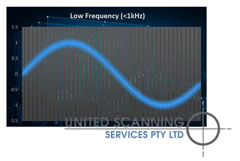
Figure 2: Graphing a low frequency signal
Where the frequency is below 1 kHz, the line must have low resistance and the circuit must be good. Low frequency signals don’t travel well when there are poor connections, or breaks in the line, high resistance and very dry soil. In addition, low frequencies are prone to being masked or tainted by ambient noise such as other sources of radio frequency signals.
Low frequency signals have the advantage that they travel very long distances without noticeably attenuating. In addition, low frequencies will not jump into other pipes or cables like higher frequencies.
Medium Frequencies (From 1kHz to 40kHz)
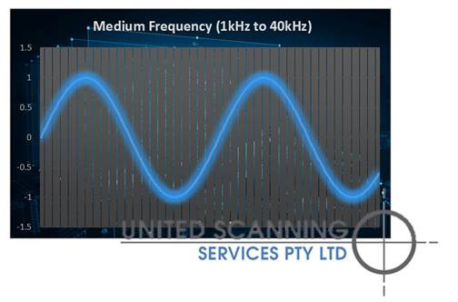
Figure 3: Graphing a medium frequency signal
Frequencies in this range are stronger and less prone to being drowned out by ambient noise. Unlike higher frequencies, signals in this range are less prone to signal bleed where, the signal bleeds into the surrounding soil and other nearby conductive lines, cables and pipes.
They are also more tolerant of cable faults and higher resistance.
High Frequencies (40kHz to 300kHz)
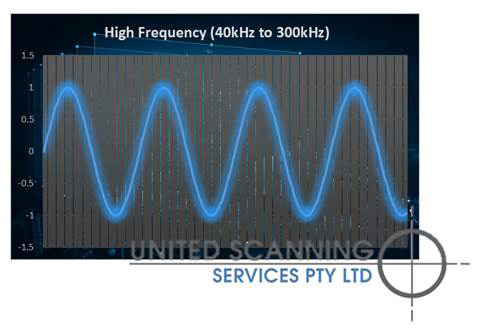
Figure 4: Graphing a high frequency signal
High frequency signals can be used to detect and much more challenging lines like dead ended cables, cables with breaks or cables with poor grounding. This range can also be used when the cable is heavily insulated or has high resistance joints (as may be the case with conductive pipes that have been glued together). High frequency signals are more likely to jump any breaks or over insulation and allow the signal to be detected further downstream.
Unfortunately, high frequencies also suffer from a high level of signal bleed into the surround soil and services. This significantly reduces its effective range and can compromise the accuracy of detection. High frequencies are more challenging in areas that are more congested as the signal may jump or couple with nearby conductors. This means that great care needs to be taken that the line being traced using a signal is in fact the target line or cable and not an adjacent one that the signal has jumped to.
Very High Frequencies (300kHz and above)
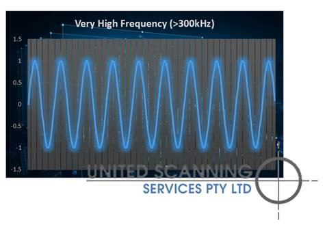
Figure 5: Graphing a very high frequency signal
Great care is taken when using very high frequencies. These are used as a last resort when the line, pipe or cable is high resistive or damaged. These frequencies can easily flow through the soil, particularly wet or damp soil and the through any other buried conductors. These signals belled heavily into the ground, significantly limiting the distance over which they are useful.
One use for very high frequency signals in this context is as a final check in an area for other conductors before excavation begins. Once all known pipes, lines and cables have been traced, very high frequencies can be used to eliminate the possibility of the presence of other conductive lines.
As a rule of thumb, a United Scanning technician will select the lowest frequency that will produce a traceable signal over the distance required to be traced. The lower the signal, the longer the distance the signal is useful over and the less likely the technician is to trace a line that is not the target line.
United Scanning’s technicians possess the experience, the technology and the intuition to make the science of your cable locating, line locating and pipe tracing jobs look like an art form.