
Half Cell Potential Testing
While United Scanning work on many green field sites and new construction projects, our clients also call us to help answer questions about more mature projects and structures. The questions are different when a structure has been long established to when it is being constructed or is new. Clients are no longer checking for construction defects but are concerned with the effect of time and use and the influence of these on the durability and structural integrity of the structure.
A vital component of any concrete structure is the reinforcement. Concrete as a material is very good at handling compressive load, but tension or shear loading tend to crack and fracture the concrete. The addition of reinforcing in concrete goes some way towards addressing this limitation in concrete, allowing it to better resist tension and shear loading, complementing its compressive strength.
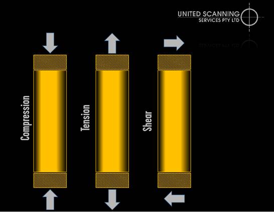
Figure 1: Different types of load
While reinforcement does allow concrete to handle stresses it would not otherwise resist well, the addition of steel rods into the concrete does have some side effects. Steel, unlike concrete, is prone to corrosion and unfortunately, most concretes are porous and can allow water in.
In addition, as concrete ages, it degrades in a variety of ways, a number of which have consequences for the steel reinforcing. One such degradation process is carbonation, where the carbon dioxide in the air gradually reacts with the concrete to form calcium carbonate in the concrete. As this process continues the alkalinity of the concrete increases and this build-up reduces the natural corrosion resistant properties that the concrete possesses. When new, the pH of the concrete is as high as 13.5, but over time falls, and once the pH of the concrete is below 10, corrosion is promoted.
Chlorides present in the concrete mix can also contribute to reinforcement corrosion, as can ingress of sulphates into the concrete. Together these factors can work to reduce the corrosion resistance of the bond between the concrete and the reinforcement.
Because the concrete conceals the reinforcement, it can be very challenging for clients to assess the level of corrosion present in the structure that they are responsible for and the obvious solution, digging up some of the reinforcement, is very damaging and at best can only partly answer the question. This is where United Scanning can help.
One test that United Scanning can perform for clients is the measurement of electrical potentials in the reinforcement within concrete. This test is often referred to as a Half Cell Potential test and it provides an indicator of the level of corrosion or corrosive potential within the concrete. It is particularly useful in exposed concrete structures like bridges, piers, jetties and multi-level car-parks.
Corrosion is an electro chemical process that occurs typically when oxygen and moisture are present in the concrete. The corrosion itself is an exchange of energy between the concrete and the reinforcing steel and the potential for this exchange to occur may differ across a structure. The energy levels (potential) of different areas of the concrete can be measured by comparing them to a reference electrode or half cell with a stable and known electrical potential. Areas with a high probability of corrosion can then be mapped and on the basis of the results, further investigation or remediation performed.
Testing the potential is relatively straight forward process, although it does require the exposure of the reinforcing at points within the structure. This may be slightly invasive and require the removal of the cover from over the reinforcement. However, only a small amount of the reinforcement needs to be exposed; just enough to attach a probe to.
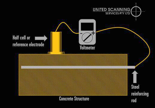
Figure 2: Diagram of Half Cell Potential test setup
Once the reinforcement is exposed, the reference electrode is connected to the negative terminal of a high impedance voltmeter. The positive terminal of the voltmeter is connected to the positive terminal of the voltmeter. A grid is marked along the structure and the reference electrode is placed at regular intervals on the grid. At each interval, readings are taken as the electrode that has been placed on the concrete closes the circuit and the voltmeter measures the electrical potential difference between the half cell and the reinforcement closest to that point.
These Half Cell Potential (HCP) values can then plotted on a schematic diagram of the structure to provide a map of the potentials across the structure, providing our client with a clear perspective on which areas of the reinforcement are likely degraded through corrosion and which are not.
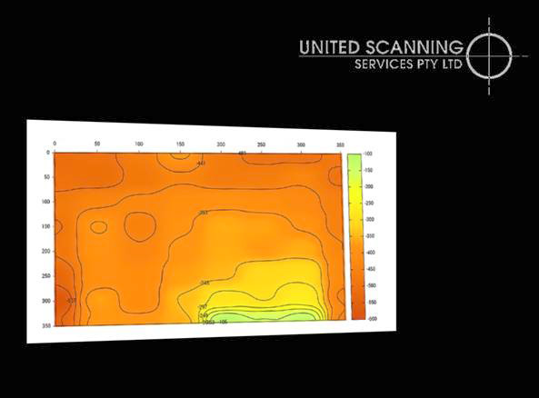
Figure 3: Half Cell Potential readings mapped
According to the ATSM standard C876, guidelines from the US that describe a standard methodology for testing half-cell potentials, where the potential is less than -350mV, there is a greater than 90% chance that corrosion is active. There the potential is greater than -200mV, these is a less than 10% chance that the reinforcement is corroding. Anything in between these values can be described as an area of uncertain corrosive activity.
| Value (mV) | < -500mV | < -350mV | -350mV to -200mV | > -200mV |
| Interpretation | Severe corrosion | Corrosion likely | Uncertain | Corrosion unlikely |
| Chance of corrosion | >90% | >90% | >10% and <90% | <10% |
Based on this information, our clients are able assess potential causes of corrosion, determining why one area may suffer more than another. They can also perform works on this basis to mitigate corrosion and remediate existing degradation, thus prolonging the life of the structure.